For sale a significantly rare mid Eighteenth Century James Watt perspective machine by John Miller of Edinburgh.
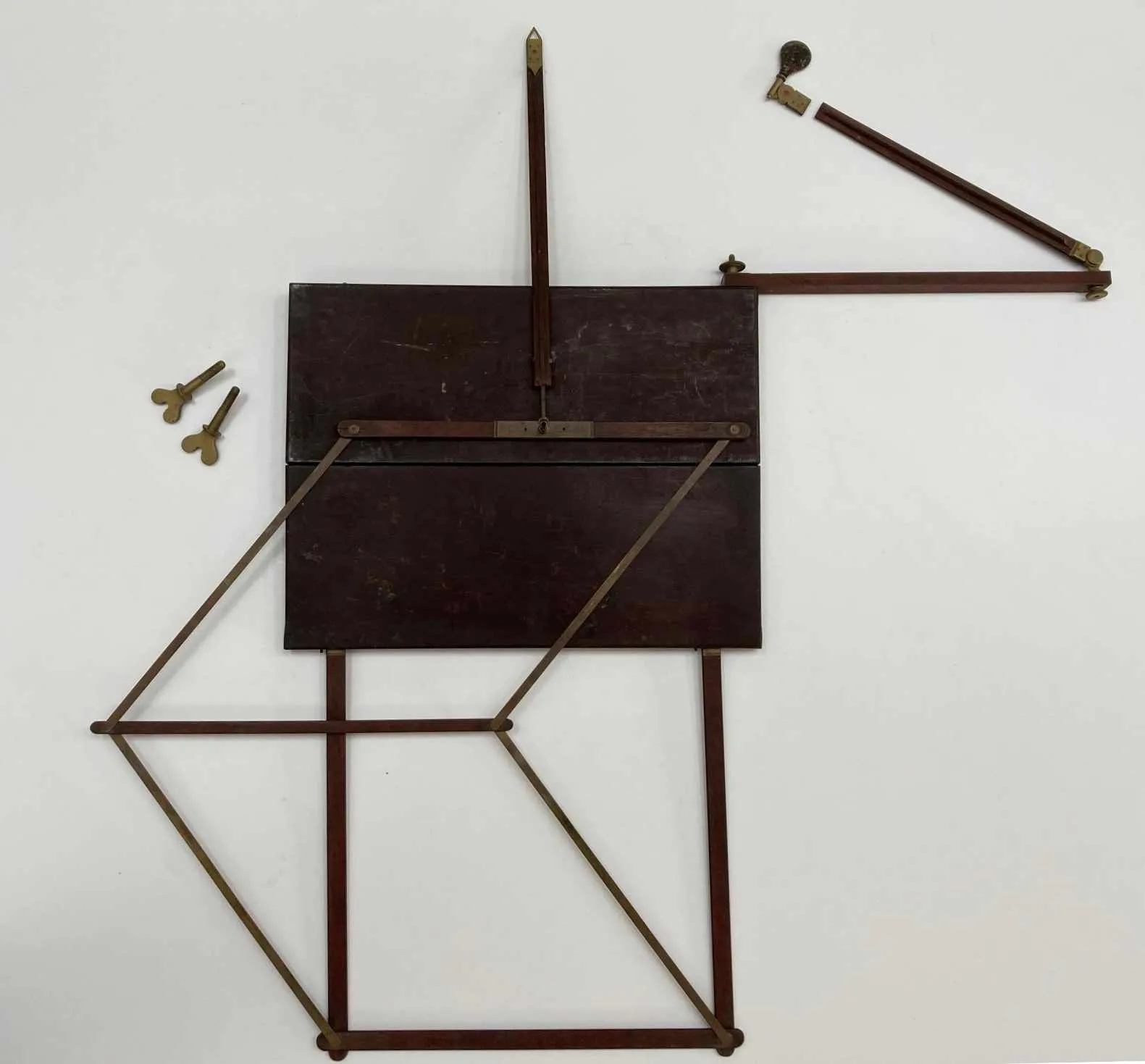
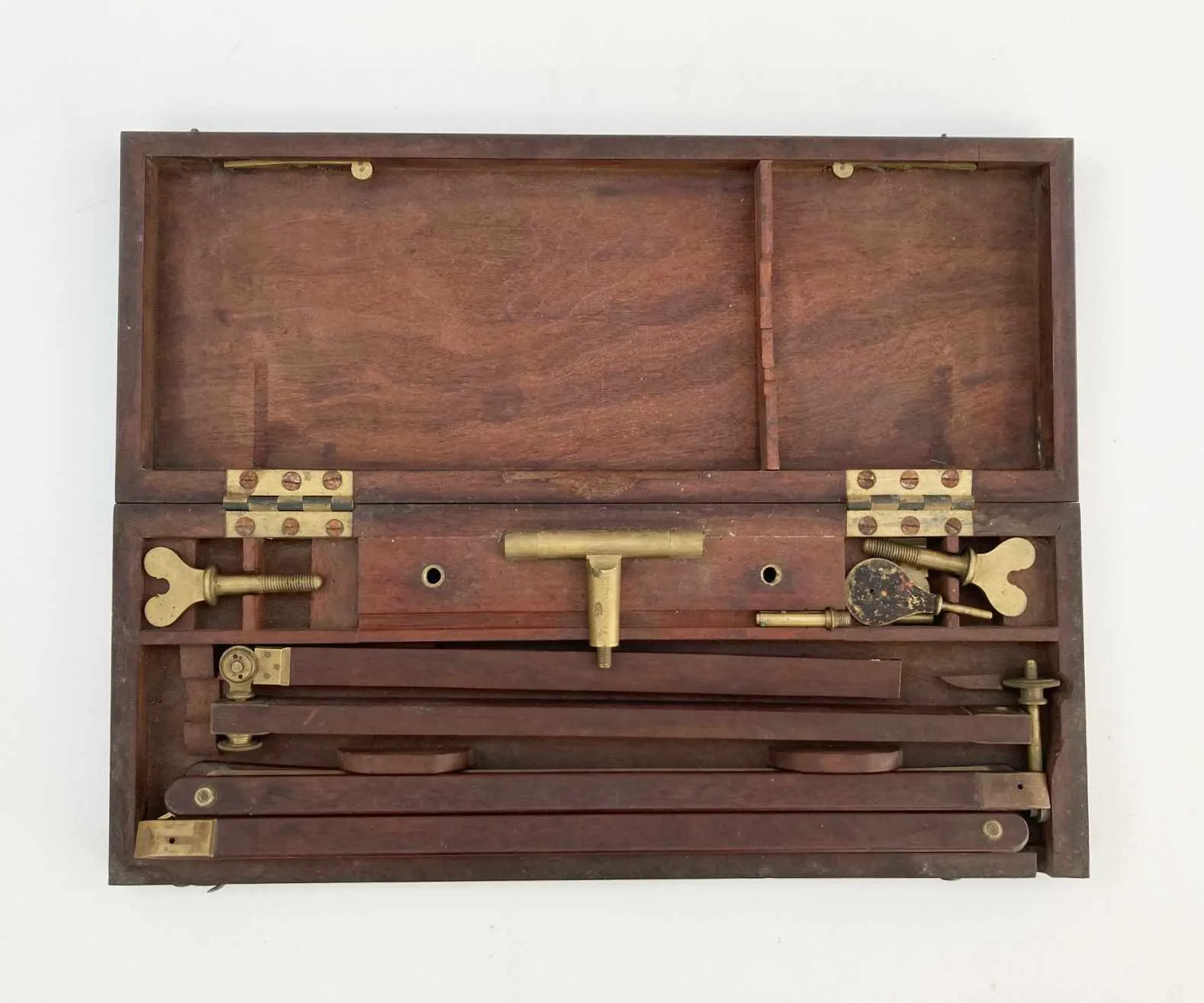
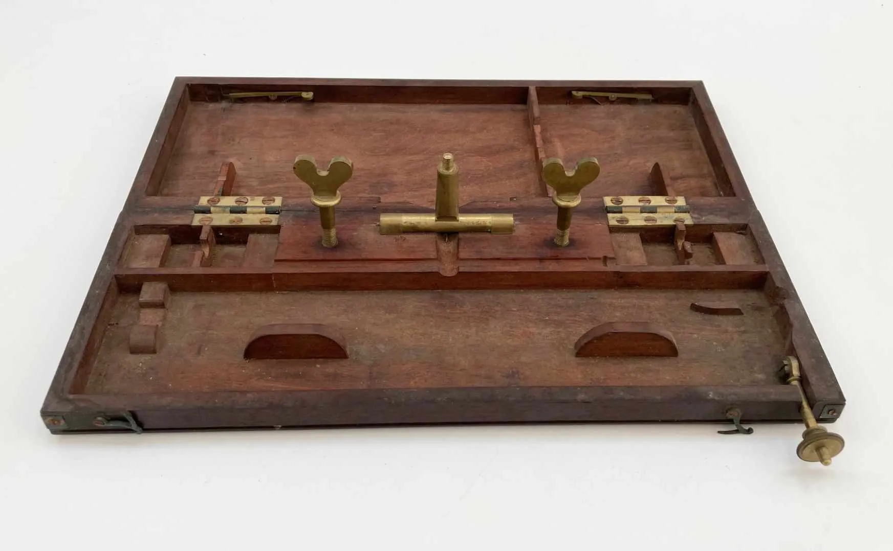
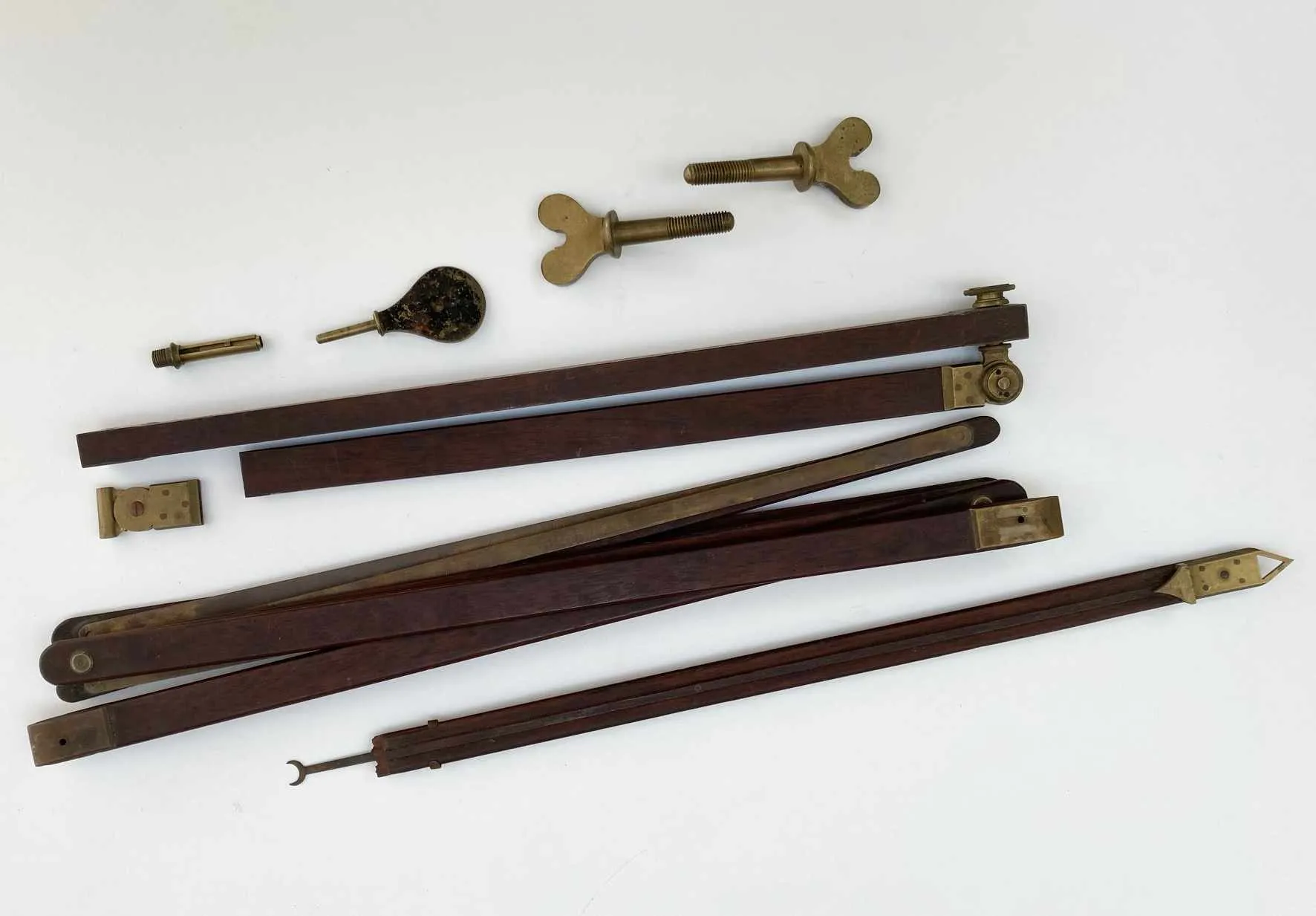
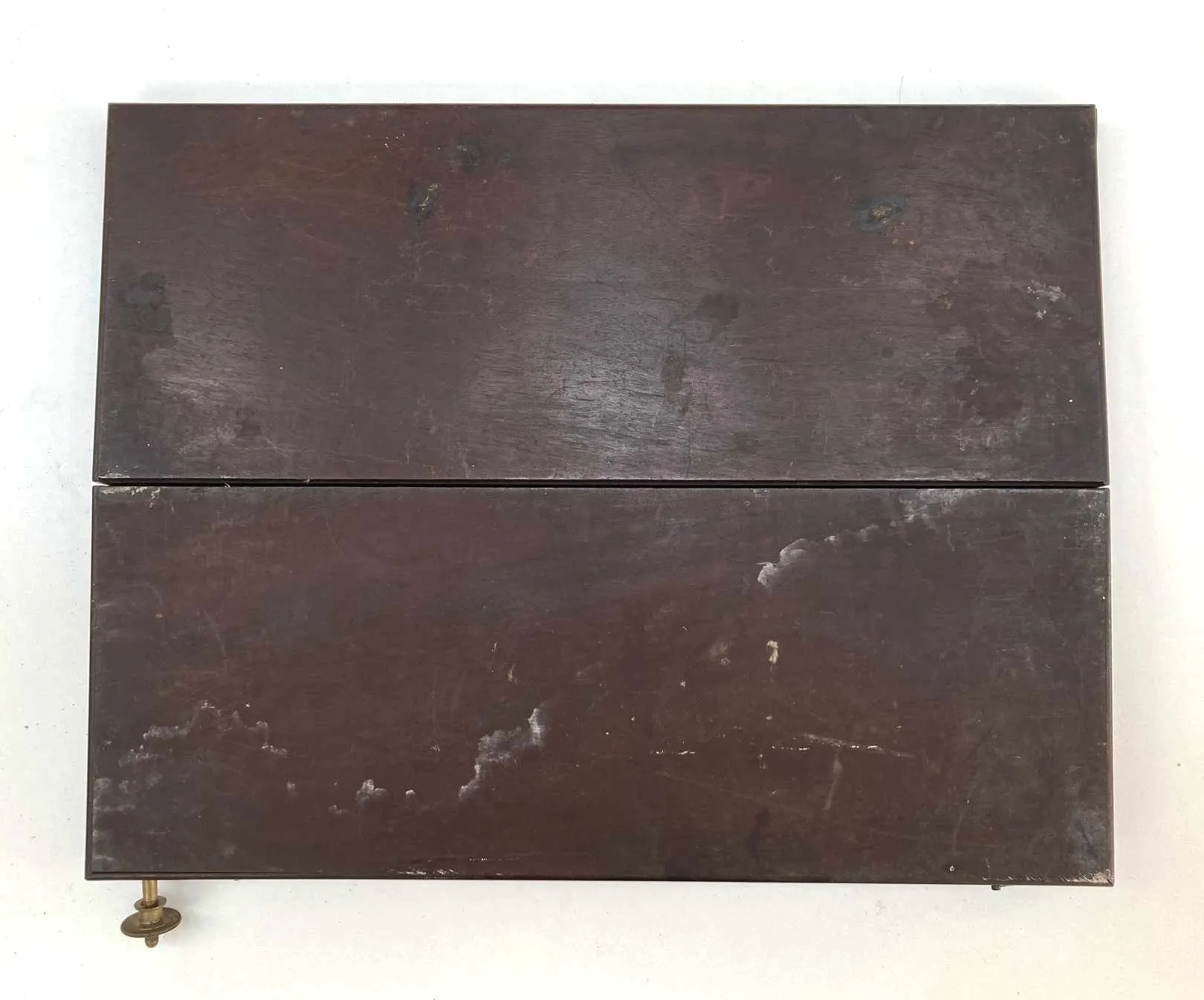
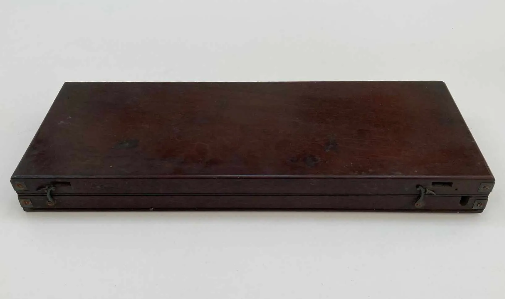
This unusual instrument is provided in a hinged mahogany case which when laid flat acts as a surface on which a piece of paper can be placed. The open face would have been attached to a tripod and through to the body by means of the two brass wingnut screw. The central bolt would have been placed over the central strut and secured, it is hinged in order to allow for movement of the tripod. A screw and nut are affixed to the top side of interior and a slit is cut in the case to allow for it to be folded out to the extrerior and on which is placed a two part mahogany and brass arm on to which a sight is placed. This acts as an adjustable eyepiece for sighting the subject of the intended drawing. (note that all of the pieces are present for this section but the sight holder has come away from the arm)
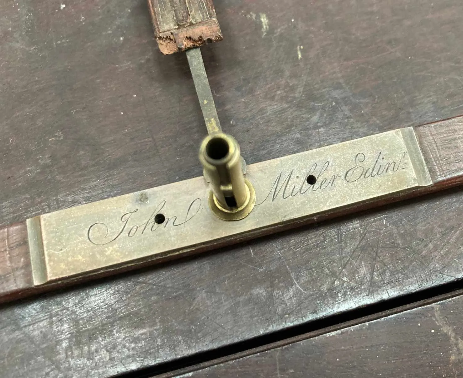
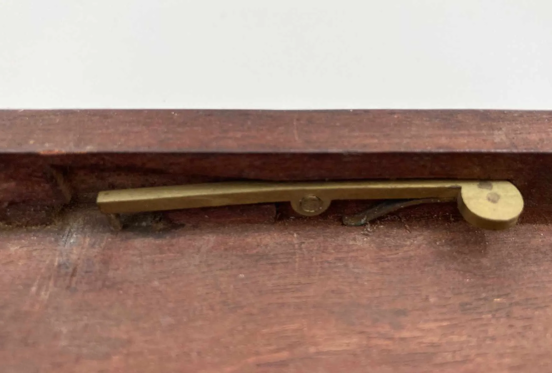
On the underside of the lower lid are cut two further slits into which the arms of a double parallel rule are inserted and locked in with sprung pin clips on the interior, This allows for stability of the parallel rule when in use. The brass section of this piece is engraved to “John Miller Edinburgh”, the central hole would have been used to secure an upright strut (t-bar connector is missing also) which contains further arm attachments for sighting various angles. It would also have been fitted with a pencil, the holder for which is present in the case.
Watt is known to have made a few of these himself and I can find only a single example of one of these rare instruments (by any maker) which is contained within The Science Museum’s collection. Watt relates that George Adams also started to manufacture these in London very shortly afterwards without his permission although Watt never sought a patent for it. He relates that,
“George Adams copied and made them for sale, putting his own name on them; as I have been told, in a book which he published, describing various instruments, he took the credit of the invention to himself, or expressed himself so as to leave that supposable: but I have not seen the book as far as I can remember, but have seen the instruments with his name on them”.
As we will see in the biographical section later in the description, Miller worked for George Adams from 1766 to 1769 so it is certain that Miller himself took Watt’s idea back to Scotland with him in 1769 and also began to make them on his own account.
A more detailed description of the instrument written by Watt himself is provided below.
Description of a New Perspective Machine
“The perspective machine was invented about 1765, in consequence of my friend Dr James Lind having brought from India a machine invented by an English gentleman there, I believe a Mr Hurst. It consisted of a board fixed on three legs perpendicularly, upon which, close to the bottom and near the ends, were placed two small friction wheels, upon which a horizontal ruler rested, and could be moved endwise horizontally. This ruler was about twice the length of the board. On the middle of this ruler was fixed perpendicularly another ruler, reaching a little above the upper edge of the board; and in this last ruler there was a groove, similar to that of the slip of a sliding rule, which was also, like that, furnished with a slider, made to move freely up and down in it; and the upper end being pointed, served for an index.
In the bottom of the groove in the perpendicular ruler, there was a slit cut quite through the ruler, nearly from one end to the other. In the lower end of the slider was fixed a pencil, the point of which reached quite through the ruler to the paper to be drawn upon, which was stretched upon the board. An arm projecting forwards was fixed to one of the upper corners of the board (I do not remember how), and upon its end nearest the draughtsman, it carried a sight or eye-piece, consisting of a small piece of metal with a hole in it; and this eye-piece was elevated about half the width of the board above its upper edge. The rulers, sliders, &c. were made of brass, and were
consequently heavy, but they moved easily on the pullies or friction wheels.
In using the machine, the board being placed at right angles to a line supposed to be drawn from the middle of the object which was to be delineated, and the sight adjusted so as to give a proper scale, the socket of the pencil was taken in the hand, the eye applied to the sight, and the index or acute top of the slider was made to travel over the lines of the object to be delineated, which it was enabled to do by a composition of the horizontal motion of the lower ruler on the wheels, and the perpendicular motion of the slider on the upright ruler. The pencil then described the lines upon the paper.
This instrument very readily described perpendicular or horizontal lines, as these accorded best with its natural motions; but in diagonal or curved lines, it was difficult to make the index follow them exactly, and the whole motions were heavy and embarrassing to the hand, and the instrument itself also was heavy and too bulky.
I wished to make a machine more portable and easier in its use, and at the suggestion of my friend Mr John Robison, (afterwards Professor Robison), I turned my thoughts to the double-parallel ruler, an instrument then very little known, and, I believe, not at all used. After some reflection, I contrived
the means of applying it to this purpose, and of making the machine extremely light and portable.
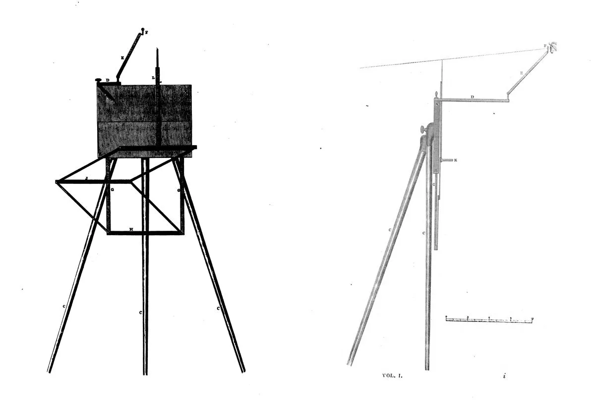
The machine consisted of a box, about an inch and a half deep on the outside, 13 inches long, and 5 inches wide, and hinged so, that when opened it formed a flat board, A, B, Plate VII. fíg. 7. and 8., of 13 inches long and 10 inches wide, on which the paper was stretched. It was kept open by means of
three legs, C, C, C, which were fastened to the back part of it, and served to support it at a proper height. From the right hand upper corner of this box or board, a jointed arm, D E, projected forward to carry the eye-piece or sight, F, which could, by means of the joints, be adjusted higher or lower, nearer to or farther from the board, as might be required. To the lower edge of the board were attached two thin slips of wood, G, G, 10 inches long and 10 inches apart, and to the lower ends of
these slips was attached the lower side of a double parallel ruler, H, I, K, every member of which was 10 inches long between centres; so that when fully open, it formed two squares, joined by one side of each, and in other states formed lozenges, or rhombuses of different degrees of obliquity. This
double parallelogram was formed partly of thin slips of wood, H, I, K, and partly of brass much hammer-hardened, and all very light.
To the middle, K, of the upper side of the higher parallelogram was fixed, at right angles upwards, another slip of wood, L, about 11 inches long, and ending in a brass point, which served for an index, which, by the construction, could be moved equally easily in every direction, and with very little friction, and at the same time all the positions of the rulers were always parallel to each other. A pencil, pressed upon by a spring, was fixed in the junction of the perpendicular slip or index at K.
A paper being stretched upon the board, and the sight being moved to a proper distance from the board, generally about 18 inches, the hand being applied to the pencil socket, (for the pencil was not pressed upon by the hand), the upper point of the index was led along the lines of the objects intended to be delineated; and when perpendicular lines occurred, the index pointing to the upper end of them, the finger of the left hand being applied to the board touching the perpendicular slip, and the pencil drawn downwards, the line would be straight, and in the same way the horizontal slip served as a guide for horizontal lines. All others were drawn by the eye guiding the index, and, if the paper was smooth, could be drawn very correctly.
The whole of the double parallelogram and its attached slips, (which latter were contrived to be easily separated from the board), were made capable of being readily folded up, so as to occupy
only a small space in the box, formed by the board when folded up. The sight-piece also folded up, and readily found its place in the box, which also contained screws for fixing on the legs of the instrument, and the box, when shut, could be put into a great-coat pocket. The three legs were made of tinned iron, tapering, and every one a little smaller than another, so that they went into one another, and formed a walking stick about 4 1/2 feet long.
I made many of these instruments about the time mentioned, perhaps from fifty to eighty ; they went to various parts of the world. Among other places several went to London, where George Adams senior copied and made them for sale.”
The maker of this instrument, John Miller (1746 – 1815) was the son of an Edinburgh turner, also a John Miller. Aside from his Father’s stated vocation, John Miller senior was very much involved in the scientific community in Scotland and extant examples of his work on county measurement standards still exist. He is also known to have worked as an experimental assistant to Dr John Robison (mentioned in the above quote from Watt), Professor of Natural Philosophy at Edinburgh so it is certain that John Miller the younger was surrounded by the most learned and intellectual people in Edinburgh from a young age.
It has been suggested that Miller was apprenticed to George Adams of Fleet Street but it seems most likely that Miller undertook an apprenticeship in Edinburgh with the noted instrument maker John Yeaman who was known to John’s Father and also involved with The Philosophical Society of Edinburgh. Miller certainly worked for Adams in London from about 1766 through to 1769 and was probably introduced to Adams through the patronage of Robison again. As mentioned earlier, this is the same time as James Watts had invented his new perspective machine and the same time in which Adams was starting to produce copies of Watt’s instrument.
Miller’s prowess as an instrument maker honed in the workshops of the London instrument maker to George III would have provided him with an instant customer base. Notably, he gained commissions for telescopes from the Edinburgh physican Dr James Lind who was the original inspiration for Watt’s perspective machine after he returned from India with a similar example, producing instruments to observe the transit of Venus in 1769.
In 1772, Miller’s sister married a printer, John Adie with whom she had two children. Alexander Adie was born in 1775 into difficult circumstances due to the death of his Father three months before his birth. His Mother soon remarried but she also died shortly after and Adie’s Uncle John Miller stepped in and adopted Alexander and it was under his Uncle that Adie served his apprenticeship and then continued to work for him until 1803 when the partnership of Miller & Adie was established.
The firm continued in this guise until 1822 although John Miller died in February of 1815. The subsequent long and successful business of the Adie family is too long to include here but can be found on other areas of my site.
Miller was a very capable and well connected instrument maker who is often overshadowed by Adie’s later success but he remains a significant figure in the history of Scottish instrument making.
Please note: as reflected in the earlier description, there is an area of damage to the sighting arm and the T-Bar for connecting the upright strut to the double parallel rule is also sadly missing. These could be completed or repaired using guidance from the Science Museum example (search James Watt perspective machine) but I have left this piece as it was found due to its significance and its huge rarity. The future owner may then decide whether the repair would be sensible or not but I can of course assist if the undertaking of the work was considered necessary.
A museum quality piece, circa 1770







![[BOXED] Kamen Rider Wizard: DX Wizard Ring Set 04 [BOXED] Kamen Rider Wizard: DX Wizard Ring Set 04](https://www.frostyworlq.shop/image/boxed-kamen-rider-wizard-dx-wizard-ring-set-04_1YxoPs_300x.webp)
